ROVI-3D White Paper
The architecture of ROVI-3D, which estimates the 6D pose of piled parts and picks them, and the physically based rendering (PBR) that creates its training data without on-site capture — explained with diagrams and video.
1. Summary
ROVI-3D is a vision system that looks at 3D parts piled at random in a bin with a depth camera, estimates each part's 6D pose (3 for position + 3 for orientation), and lets a robot pick them. It rests on two things.
| Key | Details |
|---|---|
| Architecture | The on-site device (ROVI-3D Vision) runs detection → 6D pose → grasp decision in real time; the training server (ROVI.net) builds the models and sends them down |
| PBR training | Physically based rendering (PBR) images are generated automatically from the part's CAD for training — from thousands up to hundreds of thousands of images, overlapping (occluded) scenes included, with labels |
ROVI-3D's 6D pose estimation model entered the TOP 10 among commercial technologies in the BOP Challenge, the global 6D pose estimation benchmark (2023).
2. Why it is hard
Bin picking — picking parts one by one from a bin they were dumped into — is one of the hardest tasks in robot vision.
| Difficulty | Details |
|---|---|
| Overlap and crossing | Parts hide and lean on each other, so only part of each is visible |
| Random pose | No fixed orientation, so all six degrees of freedom must be estimated |
| Materials | Metal and glossy surfaces make the image and depth unstable through reflections |
| Picking order | Picking a part from underneath collapses those on top — order must be judged too |
| Training data | AI training needs many images with pixel-level labels (masks, 6D poses); people practically cannot make these labels, and on-site capture costs time and money |
ROVI-3D solves the first four with its architecture and the last with PBR synthetic data.
3. ROVI-3D architecture
ROVI-3D has two parts: an on-site device and a training server.
| Part | What it does |
|---|---|
| ROVI-3D Vision (on-site device) | Detects parts and estimates their 6D pose from the colour + depth of a ToF / RGB-D camera, chooses the grasp point and order, and passes them to the robot. Real time on a compact high-performance PC |
| ROVI.net server (training) | Generates PBR training images from the part CAD automatically and trains the pose and grasp models, using common frameworks such as PyTorch |
| Data flow | Device → server: upload site data / server → device: download trained models |
| ROVIX 2.0 | Operator software — camera and hand-eye calibration, NVIDIA Isaac, ROS and Unity integration |
Here are the inference and training flows with real images.
4. 6D pose estimation — FFB6D-PBR
ROVI-3D's pose estimation is the FFB6D architecture (Full Flow Bidirectional 6D, He et al., CVPR 2021) trained on PBR synthetic data (FFB6D-PBR).
- Two inputs: the colour image carries the surface's texture and colour (appearance); the point cloud from depth carries its shape (geometry).
- Bidirectional fusion at every layer: most methods merge the two once at the end; FFB6D exchanges appearance ↔ geometry at every layer. When reflections disturb the image, geometry helps; when depth is lacking, appearance helps.
- 3D keypoint voting: every point votes for the location of predefined keypoints on the part surface. Even when part of it is hidden, the visible points' votes find the keypoints, so it copes with overlapping parts.
- Least-squares fit: matching the found 3D keypoints with the CAD model's keypoints gives the 6D pose (R, t).
5. Grasp decision
Knowing the pose still leaves where, and in what order to pick.
- Grasp model (deep reinforcement learning): picks a point and direction where the gripper can hold the part securely, given its pose and surroundings — a reinforcement-learning model that learns from many grasp attempts, improving bin picking of overlapping parts.
- Work order: among overlapping and crossing parts, start with those on top that do not disturb others — the robot decides the order itself.
- Robot link: hand-eye calibration converts the pose from camera to robot coordinates.
6. What physically based rendering (PBR) is
PBR (Physically Based Rendering) makes images by computing how light is reflected and absorbed at surfaces in line with physics. It is the same technology behind realistic game and film graphics; for AI training, what matters is that it produces images close to what a real camera would capture.
| PBR element | Meaning |
|---|---|
| Energy conservation | Reflected plus diffuse light can never exceed the incoming light — brightness stays physically right |
| Microfacet reflection (GGX) | Roughness sets the size and sharpness of highlights |
| Fresnel reflection | Reflection grows at grazing angles — metals reflect in their own colour, plastics give about 4 % white reflection |
| Metallic | Metals only reflect, with no diffuse light; non-metals give diffuse light in the surface colour + white reflection |
| Shadows and interreflection | Soft shadows depending on light size, light bouncing between objects |
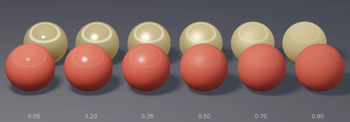
Give a part's CAD model just its colour, metallic and roughness, and the glint of a metal bracket or the soft sheen of a plastic housing is reproduced close to reality. That is why a model trained on synthetic images also works on real camera images.
7. Making training data with PBR
- Physics simulation: CAD parts are dropped into a virtual bin so they overlap and lean as in reality. Occluded scenes are created automatically.
- Domain randomization: light position, strength and colour, floor and bin colours, part materials, camera position and part count change from scene to scene, so the model does not get used to one environment and learns many spaces and positions.
- PBR rendering: colour and depth images are rendered with reflections and shadows.
- Automatic labels: the renderer knows where every part is, so it saves depth, object masks, 6D poses and occlusion ratios exactly, pixel by pixel. No human labelling is needed.
- Scale: thousands up to hundreds of thousands of images are generated automatically to suit the environment.
| On-site captured data | PBR synthetic data | |
|---|---|---|
| Preparation | Parts, equipment and capture time needed | Ready as soon as CAD exists |
| Labels | Human labelling — 6D poses practically impossible | Automatic from the renderer, pixel-exact |
| Volume | Hundreds to thousands of images | Thousands to hundreds of thousands |
| Variety | Only the captured environment | Light, material and layout as varied as you like |
| Overlap | Only what happens by chance | Deliberately, by physics simulation |
8. From simulation to the site
Models trained on synthetic data and the robot's motions are checked first in a digital twin. ROVI-3D and AI ToolBox work with NVIDIA Isaac Sim, Unity and ROS, so robot motions in simulation can be carried over to the real robot.
- The key is narrowing the sim-to-real gap: PBR rendering narrows the image gap, domain randomization the environment gap, and hand-eye calibration the coordinate gap.
- When scenes with weak results appear on site (particular lighting, materials or layouts), those conditions are recreated in simulation to add data.
9. Strengths and limits
Strengths
| Strength | Why |
|---|---|
| Copes with overlapping parts | Keypoint voting estimates pose from partial views; occluded scenes are learned in advance from training data |
| Minimal on-site capture and labelling | PBR data generated automatically from CAD — new parts can be added quickly |
| Appearance + geometry | Colour and depth fused at every layer — handles both reflective and textureless parts |
| Down to picking order | Grasp model and work-order decision reduce collapses and collisions |
| Simulation link | Isaac, Unity, ROS — verified first in a digital twin |
Limits
| Limit | Details | What to do |
|---|---|---|
| CAD needed | PBR data requires a 3D model of the part | Obtain a model by 3D scanning |
| Clear or strongly reflective parts | The depth camera itself loses depth | Polarization-camera-based ROVI-Polar (in development) |
| Sim-to-real gap | Performance drops if materials or lighting differ greatly from reality | Domain randomization, adding site data |
| Computing | Real-time inference needs a GPU-class PC | Compact high-performance PC, Jetson |
| Maturity | POC stage | Site POCs under way (chapter 10) |
10. Applications and maturity
| Item | Details |
|---|---|
| Applications | Vision guided robot (VGR), AI 6D pose estimation, AI grasping and 3D bin picking |
| Maturity | POC — development completed (2023) |
| POCs under way | Myungshin (Gunsan), LG Innotek (Startup TechBlaze) |
| Benchmark | BOP Challenge 6D pose estimation — TOP 10 among commercial technologies worldwide (2023) |
Where the 2D-camera-based ROVI-2D/2.5D handles parts of known shape quickly and at low cost, ROVI-3D takes 3D parts piled at random. Clear parts are for ROVI-Polar, and AI ToolBox brings the vision systems together on one platform.
11. Configuration
| Item | Details |
|---|---|
| Camera | ToF or RGB-D camera |
| Device | High-performance barebone PC |
| UX | ROVIX 2.0 — hand-eye and camera calibration, NVIDIA Isaac, ROS and Unity integration |
| OS | Ubuntu 18.04 or later / Windows |
| Training | ROVI.net server — PBR data generation, pose and grasp model training |
Send application review requests through floyd.kr contact.
12. Glossary
| Term | Meaning |
|---|---|
| 6D pose | An object's position (x, y, z) + orientation (rotation about 3 axes) |
| Bin picking | Picking parts one by one from a bin they were put into at random |
| RGB-D, ToF | A camera giving colour and depth together; a camera measuring depth from the round-trip time of light |
| Point cloud | A depth image turned into a set of 3D points |
| Keypoint | A predefined reference point on an object's surface — the pose is computed from where these points are |
| PBR | Physically based rendering. Making images by computing light reflection in line with physics |
| Microfacet, roughness | The tiny facets making up a surface; how scattered those facets are |
| Metallic | Whether a material is metal (1) or not (0) — sets the balance of reflection and diffuse light |
| Domain randomization | Randomly varying light, material, camera and so on in synthetic scenes so the model learns many environments |
| Digital twin | A virtual model reproducing real equipment or robots |
| BOP Challenge | The international benchmark for 6D pose estimation |